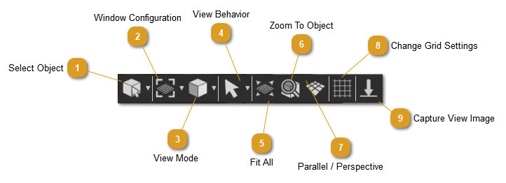
Regardless of the selected workbench, this toolbar will always be there at the bottom of the 3D area. This toolbar contains several functions that controls the behavior and appearance of the 3D area, as well as several tools for navigation and selection. It provides the user with different functions to set the view of the 3D area.
Select Object ( Pick Mode)
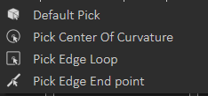
The Default Pick mode in SimLab Composer returns the location and the normal direction at the selection point. The geometry at the picked location will be selected in the Object Tree, and its bounding box will be displayed in the 3D area.
The user can change from the Default Pick to any of the following:
Pick Center Of Curvature: picking a curve will highlight the curve, and display its center normal.
Pick Edge Loop: picking an edge will highlight its loop, and display its center normal.
Pick Edge End Point: picking an edge will highlight the edge and return the normal of the closest point to selection.
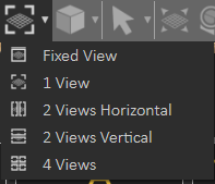
Window Configuration
This button allows the user to select the number of views, in the 3D area. The user can select to have:
Views can also be displayed by pulling the right and bottom edges of the 3D area.
View Mode
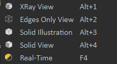
The default view mode in SimLab Composer is the Solid View, which displays solid models with edges hidden. The user can change the view mode to any of the available modes from this menu.
1. XRay View; gives x-ray effect to the models in the scene.
2. Edges Only View; displays only the edges of the models, in the scene.
3. Solid Illustration; displays models in solid view, with their edges illustrated.
4. Solid View; displays models in shaded solid view.
5. Real Time; starts real time rendering for the 3D models in the scene
View Behavior
In this menu the user can set the behavior of the mouse while interacting with the scense.
Default view behavior
The mouse behavior will be as shown in the table below:
Navigation
Mouse Button
Pan
Middle mouse button
Rotate
Left mouse button
Zoom
Right mouse button
Camera Pan
Changes the behavior of the left mouse button, to Pan.
Camera Zoom
Changes the behavior of the left mouse button, to Zoom.
Rubber band
This function changes the selection mode in the 3D area and it has three options:
Rubber Band Selection: Changes the selection icon to a square band, allowing the user to window select more than one geometry in the 3D area.
Append To Current Selection: The selection icon will show a ‘+’ sign inside the square band. The user can window select more geometry in a different section of the 3D scene, without losing the previous selection.
Remove from Current Selection: With a ‘-‘ sign added to the band, the user can remove geometry form selection, without losing previous selections.
Fit all
Updates camera to fit all geometry in the scene within the active view area.
Zoom to Object
Updates the camera in the active viewport, to zoom to the selected object. In case the user presses the button without selecting an object, a message will be displayed on top of the Setup Toolbar asking him to do so.
Switch Between Parallel and Perspective View
Switches the camera between perspective and parallel modes, in the active viewport. For engineers who are used to parallel mode, this option would be helpful.
Capture View image
Captures an image for the current view from the scene, and opens a dialog to save it.