|
|
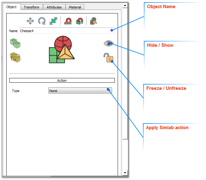
When geometry is selected in the 3D area in any workbench, this panel will display four tabs describing the selected geometry. The user can change the properties in this panel as following:
|
|
|
|
|
|
|
|
|
Object Tab:
|
|
|
In this tab the user can change the selected object name property. Other object properties that can be set in this tab include:
|
|
|
Hide/Show: by clicking this icon the user can hide/show the selected object in the 3D area. These two functions are available in the Object tab of the Scene Building workbench.
Freeze/UnFreeze: freezing the selected object will lock its position/orientation in the 3D area. All transformation functions will NOT be applicable to it, until this icon is clicked again to unfreeze it. These two functions are available in the Object tab of the Scene Building workbench.
Apply Actions: in this combo box, the user can select any of SimLab actions to apply to the selected object. Applied actions can be exported to 3D PDF files, as well as HTML (Web GL).
|
|
|
SimLab Actions:
|
|
|
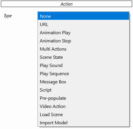
SimLab Composer supports a number of predefined actions that can be executed upon clicking a 3D model, or clicking Templates’ elements. Advanced users can write their own script to define new actions. SimLab actions can be executed in 3D PDF, and HTML files.
|
|
|
|
Action
|
Effect
|
|
URL
|
Links 3D geometry OR Template element with the entered web address, that will be opened On Click.
|
|
Animation Play
|
Stops playing scene’s animation upon clicking 3D geometry OR Template element.
|
|
Animation Stop
|
Stops playing scene’s animation upon clicking 3D geometry OR Template element.
|
|
Scene State
|
Executes a scene state upon clicking 3D geometry OR Template element. Scene states can be selected by Name or Index.
|
|
Message Box
|
Displays a message box upon clicking 3D geometry OR Template element. The user needs to enter the Message and its Title.
|
|
Script
|
Enables users to write their own script to be executed upon clicking 3D geometry OR Template element.
|
|
Pre-Populate
|
|
|
Video Action
|
allow to play, pause, seek, toggle and play duration for the video which created from Make Video function from Visual Effects menu in the VR Workbench
|
|
Load Scene
|
Run another Composer Scene from the computer or online "URL link for the scene" in the VR Viewer.
|
|
Import Model
|
Import the model into the scene during experience the VR Viewer.
| |
|
|
Multi Actions Option:
|
|
|
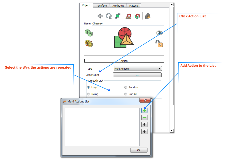
If the Multi Actions option is selected, clicking the Actions List button will open the Multi Actions List dialog. By clicking the ‘+’ button the user can enter a list of actions of different types. The order of these actions can also be changed using the up and down arrows. These actions will be executed upon clicking the selected 3D geometry, and they can also be applied in 3D PDF templates.
|
|
|
Supported ways of applying the actions list are:
|
|
|
Loop; runs the action's list upon click in order, then from start again. That is action_1, 2,3 …, then 1, 2, 3.
Swing; runs the action's list upon click in order, then backwards again. That is action_1, 2,3 … then 3, 2, 1.
Random; runs the action's list upon click randomly.
Run All; runs the action's list upon click in order one time.
|
|
|
|
|
|
Scene State:
|
|
|
Executes a scene state upon clicking 3D geometry OR Template element. Scene states can be selected by Name or Index.
|
|
|
Play Sound:
|
|
|
Utilize and employ sound effects in your exported 3D PDF files; either by assigning them to any 3D object via SimLab Composer or to 2D elements of your templates via SimLab Template Designer.
|
|
|
Play Sequence:
|
|
|
Utilize and employ Animation Sequences in your exported 3D PDF files; either by assigning them to any 3D object via SimLab Composer or to 2D elements of your templates via SimLab Template Designer.
|
|
|
|
|
|
Transform Tab:
|
|
|
In this tab the location of the selected object and its pivot can be known, as well as changed with precise values. Also Scaling uniform/non-uniform can be done for the object around its center.
|
|
|
Both the Object and its pivot have Global, and Local locations/orientations. The Global location is the location of the object’s center relative to the world’s coordinate system. The Local location changes according to the transforms performed on the object, relative to its parent.
|
|
|
Attributes Tab:
|
|
|
In this tab the user can define attributes attached to the selected geometry in the 3D scene. These attributes can be exported to 3D PDF files, and when the ‘Export Object Attributes’ option in the Advanced tab of PDF Settings dialog is checked; This can help designers communicate BIM and metadata.
|
|
|
Material Tab:
|
|
|
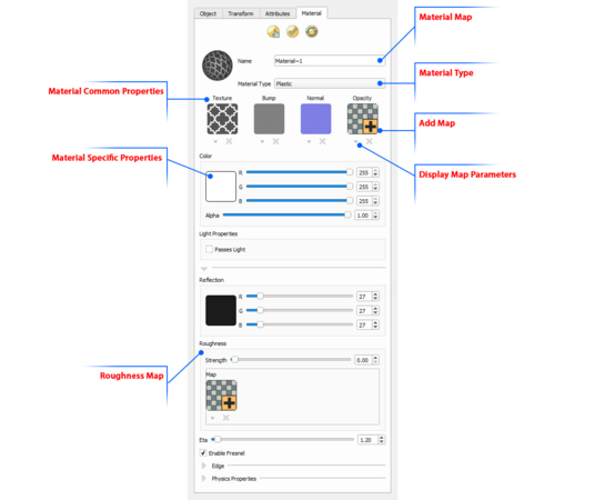
In this tab the user can change the Name and Type of the material for the selected geometry. SimLab Composer supports different material types. Common properties between different types of materials are grouped in a common place in the Properties Panel.
|
|
|
|
|
|
Different types of maps can be also applied to the material of the selected geometry, in this tab. These maps can have different effects on the look of the 3D model, thus reducing the needed modeling time and complexity. Each map has its own parameters that can be accessed by clicking the downwards arrow under the map’s image file. The user can add a map to a material by clicking the ‘+’ image, a material can also be deleted by clicking the ‘x’ button under the material image.
|
|
|
Texture Maps can be applied to any material type. The user can select to apply a texture file, and then fine tune the different parameters to get the required effect.
|
|
|
Bump Maps are used to simulate the look of geometric details on objects, so it helps the user avoid the inefficiencies when modeling these details in the geometry itself. Bump maps can be set to a texture of any format. Notice that even when a colored image is supported, it is still utilized as if it is in gray scale since bump map utilizes the intensity and not the color of the pixels.
|
|
|
The bump map basically simulates the effect of changing the surface level of the object, where bright pixels in the bump map image simulate heightened areas, and dark pixels represent lowered areas.
|
|
|
On top of the regular texture, scale, and offset properties, the bump map has one additional parameter, Strength which can be set to any positive value, and gives the user the ability to modify the bump effect where higher values make the effect stronger and more pronounced and therefore cause object to appear less smooth.
|
|
|
Normal Maps are similar to bump map, used to simulate the look of geometric details on a 3d object. The difference is that in the case of bump map, a gray scale image maps the height of the surface, whereas in the normal map a colored (RGB) image is used to map the direction of the normal in addition to its height. As such, a normal map enables finer control, but requires three channels (R,G, and B) to perform normal calculations.
|
|
|
Normal maps are generally generated by specialized software, which should give an RGB normal map image according to the desired effect by the user, in addition, lots of usable normal maps can be found on the net.
|
|
|
Opacity Maps give the user the ability to specify holes, transparent areas, and opaque areas on the mapped object. The image itself contains the opacity data in the following way:
|
|
|
Black pixels in the image map represent holes
Gray pixels represent semi-transparent areas (as brightness increases, opacity increases)
White pixels represent opaque areas
|
|
|
|
|
|
Roughness map allows the user to set an image based distribution of roughness for metal and plastic materials instead of a single value applied to whole material.
|
|
|
|
|
|
Roughness map:
|
|
|
|
|
|
|
|
|
Alpha Channel Emitter: Alpha areas of textures will turn transparent if used on an emitter.
|
|
|
|
|
|
|