|
|
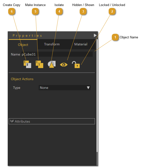
When an object is selected in the 3D area, its properties will be displayed in the Properties Panel. This panel witcontains all the properties of the selected object, where the user can perform several basic operations on it, like translate, rotate, isolate, snap, copy, and apply actions. The user can change the properties in this panel as shown below:
|
|
|
|
|
|
|
|
|
Object Tab:
|
|
|
In this tab the user can change the selected object name property, and other properties as described below:
|
|
|
Lock/Unlock, locks the selected object in the 3D area. All transformation functions will NOT be applicable to the object, until it is Unlocked.
Hide/Show; hides/shows the selected object in the 3D area.
Isolate; hides all objects in the scene except the selected object
Make Instance; creates duplicate of the object using the same materials’ structure, and same transforms as the original object.
Create copy; creates duplicate of the object without link to the original object material or transforms
Apply Actions: in this combo box, the user can select any of SimLab actions to apply to the selected object. Applied actions can be exported to 3D PDF files, as well as HTML (Web GL).
|
|
|
|
|
|
Attributes Panel:
|
|
|
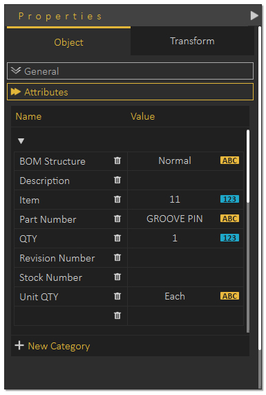
Under this panel the user can define attributes attached to the selected geometry in the 3D scene. These attributes can be exported to 3D PDF files, and when the ‘Export Object Attributes’ option in the Advanced tab of PDF Settings dialog is checked; This can help designers communicate BIM and metadata.
|
|
|
|
|
|
Transform Tab:
|
|
|
In this tab the location of the selected object and its pivot can be known, as well as changed with precise values. Also Scaling uniform / non-uniform can be done for the object around its center.
|
|
|
Both the Object and its pivot have Global, and Local locations/orientations. The Global location is the location of the object center relative to the world coordinate system. The Local location changes according to the transforms performed on the object, relative to its parent.
|
|
|
|
|
|
Material Tab:
|
|
|
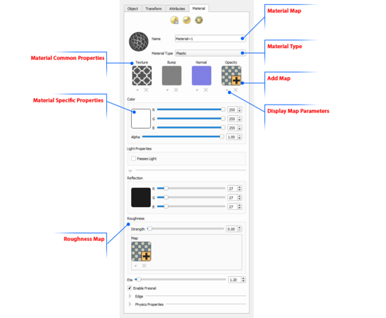
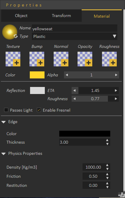
In this tab the user can change the Name and Type of the material for the selected geometry, SimLab Composer supports different material types. Common properties between different types of materials are grouped in a common place in the Properties Panel.
|
|
|
|
|
|
Different types of maps can also be applied to the material of the selected geometry, in this tab. These maps can have different effects on the look of the 3D model, thus reducing the needed modeling time and complexity. Each map has its own parameters that can be accessed by clicking the downwards arrow under the map’s image file. The user can add a map to a material by clicking the ‘+’ image, a material can also be deleted by clicking the ‘x’ button under the material image.
|
|
|
Texture Maps can be applied to any material type. The user can select to apply a texture file, and then fine tune the different parameters to get the required effect.
|
|
|
Bump Maps are used to simulate the look of geometric details on objects, so it helps the user avoid the inefficiencies when modeling these details in the geometry itself. Bump maps can be set to a texture of any format. Notice that even when a colored image is supported, it is still utilized as if it is in gray scale since bump map utilizes the intensity and not the color of the pixels.
|
|
|
The bump map basically simulates the effect of changing the surface level of the object, where bright pixels in the bump map image simulate heightened areas, and dark pixels represent lowered areas.
|
|
|
On top of the regular texture, scale, and offset properties, the bump map has one additional parameter, Strength which can be set to any positive value, and gives the user the ability to modify the bump effect where higher values make the effect stronger and more pronounced and therefore cause object to appear less smooth.
|
|
|
Normal Maps are similar to bump map, used to simulate the look of geometric details on a 3d object. The difference is that in the case of bump map, a gray scale image maps the height of the surface, whereas in the normal map a colored (RGB) image is used to map the direction of the normal in addition to its height. As such, a normal map enables finer control, but requires three channels (R,G, and B) to perform normal calculations.
|
|
|
Normal maps are generally generated by specialized software, which should give an RGB normal map image according to the desired effect by the user, in addition, lots of usable normal maps can be found on the net.
|
|
|
Opacity Maps give the user the ability to specify holes, transparent areas, and opaque areas on the mapped object. The image itself contains the opacity data in the following way:
|
|
|
Black pixels in the image map represent holes
Gray pixels represent semi-transparent areas (as brightness increases, opacity increases)
White pixels represent opaque areas
|
|
|
|
|
|
Roughness map allows the user to set an image based distribution of roughness for metal and plastic materials instead of a single value applied to whole material.
|
|
|
|
|
|
Roughness map:
|
|
|
|
|
|
|
|
|
Alpha Channel Emitter: Alpha areas of textures will turn transparent if used on an emitter.
|
|
|
|
|
|
|